updated 6th March 2011
Summary:
When the 555 Contest came about in Jan 2010 I decided that if I was going to make an entry then I would make a temperature controller. This is because I use PICs on a day-to-day making temperatures etc where I work. I'm not going to enter the contest as I want to spend some time on this, writing it up and documenting it well.
So below is the progress so far...
Concept:
So the aim is to speed control a fan with a PWM input from a stock temperature sensor - range of 20'c to 40'c.

So we have to start with an idea. this as you can see is drawn out on paper, block form, to show what chucks I need for my design. Here we have a standard NTC sensor with a resistance of 100k at 25'c. The next interesting block is the 555 frequency generator. which will need to put out a square wave in the range of 2kHz to 6kHz. I could have used a signal 555 to generate my PWM by changing the control voltage when configured as a astable. However this alters the frequency as well and well, not like a real PWM. So my first 555 generates a fixed frequency.
The second 555 acts as a monostable the is triggered by the first 555 timer. The RC network will generates aprox half the pulse width of the period of the first (50% duty). What I'll then do is apply a voltage to the control pin which will lengthen or shorten the width. As the first timer has a fixed frequency, we are effectively generating a PWM output. I've guessed the input voltages to the control pin will be from about 700mV to 4.2V.
The Amplifier will therefore have to take the NTC input and generate a voltage for the control pin as stated. I'll possible use a few POTs to tweak once I’ve got it build to adjust. I'll also need to look at stopping the output going over voltage as I know there is a small window were the 555 monostable period will get bigger than the astable, or close to it and could cause it to miss triggers. Hence I know I'll never reach 100% also.
As I should really buffer my 555's output, I'll use a FET or BJT. This will invert the signal which is fine as the NTC is inverted so to speak anyway. So my amplifier need to be non-inverting from front to back.
Design:
So once we have considered the concept stage and come up with your initial idea on how to solve the problem you next have to draw up your first circuit.

Here I have used the circuit simulator that is free to use on http://www.falstad.com/circuit/. I like this too as you do not need to install it (other than having Java installed) and is real simple to use. I could have used SPICE but this is nothing fancy and wanted to introduce something that anyone can use.
I used the data sheet of my chosen NTC sensor to find the resistance of it at 20'C and 40'C, this came out at 126k and around 51k respectively. This is shown by the two resistors that are selectable via a switch in the simulation. I then have a RC low pass filter which will help reject noise from the PWM going to the fan. The two stage opamp gives me the range and gain setting to give me the required output voltage.
Moving forward to the 555s the first give a frequency around 4kHz which is what we wanted. This is decoupled via a 100nF cap that generates the trigger pulse into the second 555. Note that it triggers on the negative pulse, there is a positive pulse from 5v up to 10v which needs filtering out, although the 555 will tolerate the blip (I think).
The Second 555 has matching 1k and 100nF caps so that when there is nothing applied to the control pin, you get around 50% duty. I then connected the output of the opamp to the control pin. When I did this I needed to teak the gain value a little - possible due to the current drawn / sourced by the 555. Again this can be tweaked in the real final circuit.
One issue to over come was the control pin going over voltage and causing odd 555 output waveform due to re-triggering time of second 555 timer. To get around this I have used a pair of diodes back to back to generate a volt drop in each direction.
Next step is to build the above and see it if works...
Build:
So after generating you circuit you need to build it. This can be done in a number of ways from a bird or rats nest of devices soldered directly to one another, or it could be a full PCB layout. However I've opted for my favourite route which is to use strip board.
Before building the board however I always plan my layout on graph paper as shown below. This lets me plan were devices will go, where to cut track and place links etc.

From this I have now built my board as shown below. Its almost 100% to the layout, I made one mistake which I had to work around but it still looks nice and guess you will have not noticed unless I had said.
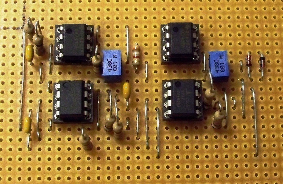
I've not powered the board up at this stage so the board shows all the ICs fitted. In the next section I'll test the board which you should first do with no expensive or difficult to remove parts fitted. Don't want to blow them up do we.!
Testing:
So over last few weeks I've had time to test the board now. First off I could not get the Monostable to work but found that connecting the ground pin to 0 volts help! Duh!
The 555's worked very well and I got good range of PWM duty out of them by feeding a voltage directly into the second 555's control pin.
The amp circuit was a bit of a fiddle. I found that I got more swing from the first opamp alone without needing the extra 741 opamp. So I have bypassed the second 741 and am now driving the control pin of the 555 straight from the first 741.
The final circuit works quite well and I think is a good example of what you can do with just a few chips.
While the 555 contest entries are now all in and the judging is taking place, just want to wish everyone the best of luck. But don't just stop using 555s because the contest is over - hopefully you can now see that you can do a lot with these chips.
Below is a short video showing the circuit running.